I recently bought a DIY Display Module using the SSD1306 Driver from Alibaba AliExpress. In this post we discuss the physical wiring from the display module to the Raspberry Pi and the SPI Mode to interface with it. The goal is to control it in a C program.
Hardware Required
- SSD1306 Module 7-pin 1.3" with with 128x32 OLED Display
- Raspberry Pi B+
- Connecting Wires
The module I got was a GME12864-83 1.3" SPI OLED SH1106 for $3.52 USD from the S+S+S+.
Display Module Pinout
What’s confusing is the silkscreen on the circuit board for the display module has SCK and SDA which are I2C Pins and not the SCLK and MOSI per the SPI spec. If the pin ends with a # that means it’s active low.
| Module Pin | Name | Description | Type |
|---|---|---|---|
| 1 | GND | Ground Pin | Power |
| 2 | VDD | CMOS Vdd 1.35V to 3.3V for IC Logic | Power |
| 3 | SCLK | SPI Serial Clock | Input |
| 4 | MOSI | SPI Master Out, Slave In | Input |
| 5 | RES# | Reset Pin. When LOW, chip will initialize. Keep HIGH for normal operation | Input |
| 6 | D/C# | Data/Command. High is to write data (pixels), Low is commands. | Input |
| 7 | CS# | Chip Select. Active Low. | Input |
This pinout is for the 4-wire SPI Interface. This interface has the benefit of being able to send either data or control using the D/C# pin and we can also support multiple display interfaces by using the CS# lines. I think it’s the best fit since it minimizes the amount of software by using more pins - which there are plenty - on the RPI.
Wiring Display Module to Raspberry Pi
| Display Module Pin | Display Module Pin Name | RPI Pin Desc | RPI Header Pin | RPI BCM Pin |
|---|---|---|---|---|
| 1 | GND | GND | 9 | |
| 2 | VDD | 3.3V | 17 | |
| 3 | SCK | SPIO SCLK | 23 | 11 |
| 4 | MOSI | SPI0 MOSI | 19 | 10 |
| 5 | RES# | GPIO5 | 29 | 5 |
| 6 | D/C# | SPI0 CE0 | 24 | 8 |
| 7 | CS# | GND | 24 | 6 |
Having the RES# wired to a GPIO line is helpful since we can reset the display. It does, however, add some more code since we not only have to use SPI in the Raspberry Pi, but also use GPIO.
See Pinout for the Raspberry Pi. Note, the BCM is the actual pin on the Broadcom chip, and not the pin on the header.
SPI Modes
Here is the SPI timing for the SSD1306.
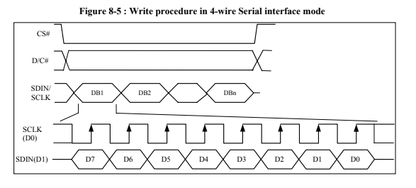
SPI Timing for SSD1306
We have the following SPI Modes. We will need to know which Mode the SSD1306 uses.
| Mode | CPOL | CPHA | Output Edge | Input Edge |
|---|---|---|---|---|
| 0 | 0 | 0 | Falling | Rising |
| 1 | 0 | 1 | Rising | Falling |
| 2 | 1 | 0 | Rising | Falling |
| 3 | 1 | 1 | Falling | Rising |
From the timing diagram in the Datasheet we can see that data is captured on the rising edge of the Clock so we know CPOL=0. For the input we can see that CPHA=0 since the data changes on the falling edge of the clock and it is valid on the rising edge of the clock.
Thus, the SSD1306 is in SPI Mode 0.
Added
raspi-config # enable spi
Was set to: pi@raspberrypi:~/rpi_ssd1306/src $ ls -l /dev/spidev0.0 crw——- 1 root root 153, 0 Mar 20 20:34 /dev/spidev0.0
Changed to
pi@raspberrypi:/rpi_ssd1306/src $ sudo chgrp spi /dev/spidev0*
pi@raspberrypi:/rpi_ssd1306/src $ sudo chmod g+rw /dev/spidev0*
pi@raspberrypi:/rpi_ssd1306/src $ ls -l /dev/spidev0.0
crw-rw—- 1 root spi 153, 0 Mar 20 20:34 /dev/spidev0.0
pi@raspberrypi:/rpi_ssd1306/src $
What’s Next?
I hope to soon post some C-code to control the SSD1306.